|
irda
interface for your mainboard
many modern mainboards have an irda connector onboard, but the required transceiver is often missing. if you can't find the exactly fitting module
for your mainboard, you can probably use a module from another mainboard if you connect it in the right way. just see the mainboard documentations (or search the web) and compare the pinouts. irda modules normally
need 4 signals: gnd, +5v, rxd and txd.
or you can build your own irda module!
all you need is a irda transceiver and some resistors and capacitors. for my mainboard, an asus
p/i-p55t2p4, i used a tfds4500 transceiver, available e.g. from conrad electronic, best.nr. 18 13 31, DM 11.95
download the datasheet for the tfds4500 which contains the appropriate schematic and more detailed information.
the following schematic and component values are from the datasheet:
on the left you see the schematic of the irda interface and on the right there is the pinout of the tfds4500 (top view).
jumper jp1 is used to choose the sensitivity of the ir receiver. high sensitivity gives a greater receiving range
but also more noise which could result in lower transmission speed.
to be able to connect the irda module to your mainboard you have to know your mainboard's pinout of the
irda connector. below you can find some pinouts from boards which are known to work with this irda module:
|
asus p/i-p55t2p4
|
|
biostar m6tlc
(submitted by j.j.a. van sikkelerus jr)
|
|
|
pin
|
signal
|
|
1 (near board edge)
|
+5V
|
|
2
|
fast rxd
(not needed)
|
|
3
|
rxd
|
|
4
|
gnd
|
|
5
|
txd
|
|
|
|
pin
|
signal
|
|
22
|
+5V
|
|
23
|
nc
|
|
24
|
rxd
|
|
25
|
gnd
|
|
26
|
txd
|
|
|
abit be-6
(submitted by biro andras)
|
|
soltek sl-75 kav und kav-x
(all signals on jumper 3)
(submitted by dirk wunderlich)
|
|
|
pin
|
signal
|
|
1
|
+5V
|
|
3
|
nc
|
|
5
|
rxd
|
|
7
|
gnd
|
|
9
|
txd
|
|
|
|
pin
|
signal
|
|
6
|
txd
|
|
7
|
gnd
|
|
8
|
rxd
|
|
9
|
nc
|
|
10
|
+5V
|
|
|
msi ms-6163 va and ms-6330
(submitted by wim westerweele and walter willaert)
|
|
gigabyte ga6bx7+
(submitted by ferenc gelegonya)
|
|
|
pin
|
signal
|
|
1
|
+5V
|
|
3
|
nc
|
|
5
|
rxd
|
|
7
|
gnd
|
|
9
|
txd
|
|
|
|
pin
|
signal
|
|
1
|
txd
|
|
2
|
gnd
|
|
3
|
rxd
|
|
4
|
nc
|
|
5
|
+5V
|
|
|
gigabyte ga-7ixe and ga-7zx
(submited by Choi, Taek-jin)
|
|
asus p3v4x
(submitted by mauro balaguer bres)
|
|
|
pin
|
signal
|
|
1
|
+5V
|
|
3
|
nc
|
|
5
|
rxd
|
|
7
|
gnd
|
|
9
|
txd
|
|
|
|
pin
|
signal
|
|
1
|
+5V
|
|
2
|
nc
|
|
3
|
rxd
|
|
4
|
gnd
|
|
5
|
txd
|
|
as you see, all boards use the same pin order! so if your board is not listed here, it could be the same. but
before you plug the module into your board you should check this with a voltmeter (or better your manual).
if you found out the pinout from your board and it is not in the same order than the one listes, please e-mail it to me, so i can inlude it here.
i want to thank all the people, who sent me the pinout of their mainboard´s irda connector!
please notice that the tfds is a smd part, but with a little bit patience you can even solder it onto a prototype board, as you can see below.
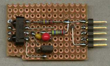
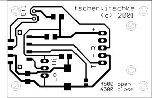
but i also made a small single sided pcb layout. download (eagle 4.0 format and 300 dpi tiff included).
after connecting the module to your mainboard, you have to load irda drivers. i just took the standard irda
driver found on the windows 98 cd which works perfectly for me.
if you have further questions or you successfully connected a self built irda module to your board please let me know.
related links:
|